 Home
Home C4AE-G / C8AE-H Section
 Head Port Positions
| Home |
C4AE-G / C8AE-H Section |
Head Port Positions |
These cross sectional cuts were made to see what the porting possibilities were for the R head and to see how the F was different from the R head. I hope these photos show clearly the similarities and differences. My comments are just that. Your feedback is welcome but if you disagree tell me why. I intend to update this with your comments even if they disagree with mine and may delete my comment and use yours, if yours seems more useful. Positive feedback is welcome also.
These heads, C5AE-F and C6AE-R, are not "virgin"; they've been used and abused. I will refer to them as MR or F and LR or R. The MR has been hit with a piston and is badly cracked collapsing the intake side of the head as well as the combustion chamber but no porting as been done to it and doesn't appear to have ever been surfaced. The LR or R has been surfaced and some of the ports opened up but others are completely stock.
The general quality of the F casting is some what better. The appearance of the F is smoother outside. Lots of little things are different and most of these differences are well documented. The F intake and exhaust valves are a bit further apart. The F combustion chamber is completely machined. The F head is cut for valve spring seats. The intake port on R is taller but the main difference in the intake ports is the R port is deeper at the bottom. The exhaust port of R is lower on the outside edge of the head; the exhaust pocket is hollow under the back side. The R has thermactor ports that are not drilled but the internal port lips are there; the end of the exhaust ports have a vertical lip which narrows the port's opening. The F oil feed to the rocker arm assembly is higher with the casting modified - the oil gallery up to the rocker stand can be readily seen.
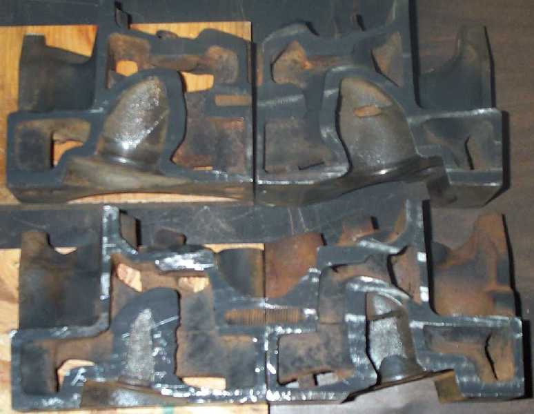
Please note that the cuts are not perfectly square either vertically or left to right. A power hack saw (or at least the ones used to make these cuts) is not able to make precision cuts. Nor are the cuts exactly in exactly the same place length wise although they are very close.
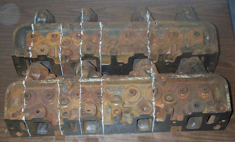
The first picture, CrossSection1a , is of both heads with the section cuts marked with white chalk. The C6AE-R is in front and has a casting date of 6B8 with "DF" and "R" between the 1 and 2 exhaust ports and "15" and "FoMoCo" between the 3 and 4 exhaust ports. The C5AF-F head has a casting date of 0K10 with "F" in a circle between the 1 and 2 exhaust ports and "FoMoCo" and "4" between the 3 and 4 exhaust ports. The cuts will be referred from left to right as cut 1 through cut 5. So the second cut from the left on the C5AE-F head would be F cut 2. The left side of this cut would be F cut 2 L.
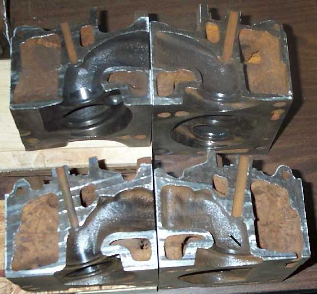
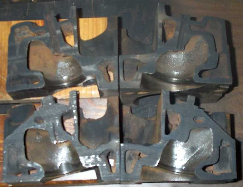
Photo Cut5-C5F-C6R which is cut right down the center of the exhaust valve guide on both heads, shows the two heads opened with exhaust port exits touching. The F head is at the top. On the R head exhaust bowl there is a pocket under the seat, which is pointed out by an arrow ithe photo. The F head is blended to the seat here. Some measurements: the F guide is 2.36 inches long, the R guide is 2.45 inches long - the tops of both guides are about even with the angle the valve cover rail makes. Seat to Intake Manifold face is 2.05 in the F and 2.21 on the R. Bowl wall thickness is 0.238 on the F and 0.268 on the R. Bowl wall thickness at the guide is 0.288 on the F and 0.300 on the R. Deck to floor on the port is 1.64 on the F and 1.40 on the R. Note that the hump in the floor for the coolant passage is very small on the F head. As this is the inside radius of the port; flow is not high here and porting here usually just hurts total flow.
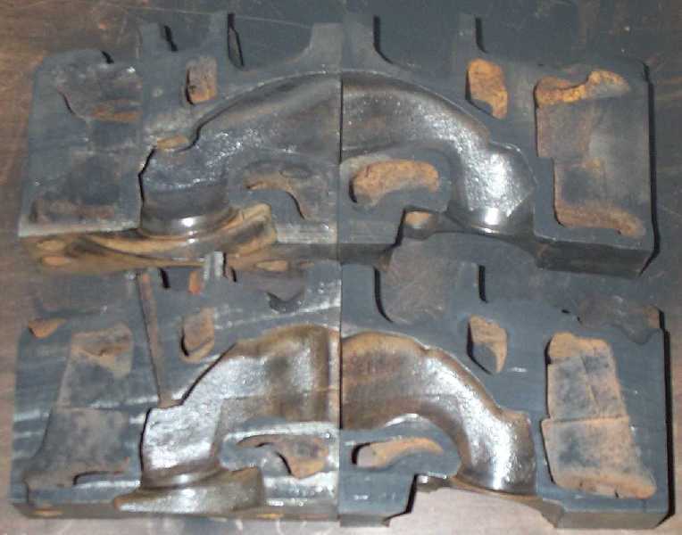
Photo Cut3-C5F-C6R which is cut near the center of the exhaust valve guide on both heads, shows the two heads opened with exhaust port exits touching. The F head is at the top. The measurements are very similar to those of Cut 5 and only the differences are given. The guide length is 2.32 on F and 2.47 on R. Bowl wall thickness is 0.236 on the F and 0.2165 on the R. Bowl wall thickness at the guide is 0.275 on the F and 0.20 on the R. Deck to floor on the port is 1.71 on the F and 1.41 on the R.
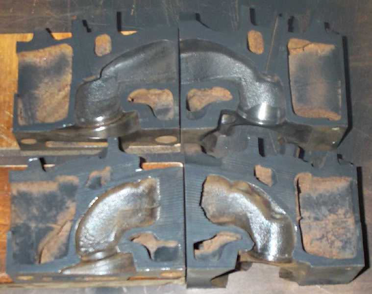
Photo Cut1-C5F-C6R which is cut near the center of the exhaust valve guide on both heads, shows the two heads opened with exhaust port exits touching. The F head is at the top. Dimensions were again similar to Cut 5 with the guide length being the most different 2.35 for F and 2.44 for R.
Photo Cut2-C5F-C6R which is cut near the intake valve guides on both heads, shows the two heads opened with intake side of the heads touching. The F head is at the top. Guide lengths are identical 2.38 inches. The bowl thickness at the right outside edge just under the seat at the thinness point is 0.23 for F and 0.18 for R. Bowl thicknes just under the seat at the inside edge just under the seat at the thinest point is 0.19 for F and 0.16 for R. Thickness of the runner is 0.27 at the thinness point near the guide, toward the valve.
Photo Cut4-C5F-C6R which is cut near the intake valve guides on both heads, shows the two heads opened with intake side of the heads touching. The F head is at the top. Very similar to cut 2.
C5AE-F and C6AE-R Cross Section Photos, Page 1