
This topic comes up monthly and either gets a too brief a reply or turns into a real argument about what should be done and, occasionally, why it should be done. I've split this into three parts. Part One is basic engine oil system theory. Part Two explores the stock FE oiling system where we find out why Ford created the Sideoiler. Part Three makes some recommendations for modifications to the oiling system.
Skip to Part Two - The FE's Oiling System or Part Three - Modifications
The oiling system is crucial to keeping the engine alive. Oil does five things. It lubricates, cools, cleans, seals and fights corrosion. The first two of these are what we'll look at in this discussion while using the FE in our examples.
The Oil System in the modern internal combustion engine is an open system or what I call a collection of controlled leaks. We create pressure at the pump, filter the oil, route the oil through many oil galleries and passages and then let the oil leak out past the machined surfaces at the cam and crankshaft bearing journals and other orifices. The oil completes its travel by splashing around the crankcase to the pan or running down some open galleries to the pan. Specifically on our FEs, it leaks out around the cam and crank bearings, along the sides of the lifters to the end of the lifter bores, out a hole in the rocker arm and also past the edges of the rocker arms. The oil splashes around to lubricate the end of the push rods and valve stems, and the timing chain and gears (since there is no gallery orifice that directly oils any of these.) The oil also cools the all of the above plus the valve springs and picks up additional heat as it travels back to the pan.
The amount of oil delivered is determined by the tightness (actually the looseness) of the fit of the machined parts. These increase (both the amount of oil delivered and the looseness) as the engine wears. When we build the engine we determine the amount of oil delivered by the finished size of the crankshaft and cam journals and their corresponding bearings, the clearance in the lifter bores and the clearance between the rocker arms and the rocker arm shaft. Most of us accept the clearances that the parts have when we buy them and never think about this. The hard core professional engine builders, however, give a lot of thought to these clearances.
Most of us worry about the amount of oil that is delivered. But the lubrication is only a part of the function of the oil. Cooling is a big part also. Large clearances mean more oil delivery for better cooling. Both the main and rod bearings like lots of oil for cooling as well as lubrication. Valve springs need lots of oil, and in fact should be bathed in oil for long high speed runs.
The size (diameter), shape (number and tightness of the bends) and length of the oil galleries controls the amount of oil flow. Obviously the size or diameter does control flow so that is not going to be argued. The shape is very important to flow. Each time the diameter of a pipe changes the turbulence induced by that change increases the flow friction or resistence.
Hollis Franks: It is Basic Flow Hydraulics! When fire departments switched from 2.5" to 3" hose, only 1/2" larger, friction loss went down 40% and the pumps worked a lot easier, and if you run the pressure back up to where it was with the smaller diameter, the flow is greatly increased. Hollis Franks
To better understand why changes in shape induce turbulence picture a busy four lane freeway. When the number of lanes is reduced to three the traffic must merge. No one is allowed to slow down as the number of cars does not decrease and therefore to handle the increased number of vehicles per lane everyone must increase their speed. And our freeways (oil gallerys) are really three dimensional with lanes above and below us, as well as on both sides. The change in speed is forced by pump pressure which does not permit a loss of oil velocity through the restriction. Of course every restriction has its flow limit so some flow loss occurs, and in turn, raises the pressure behind the restriction. Thus a restriction prevents a smooth flow while the flow volume tries to remain constant (within the capacity of the reduced gallery.)
Tight bends also induce turbulence (picture that three dimensional freeway making a tight radius turn
like that of a normal street intersection) so these tight turns are a problem also. Here's a picture
that shows the effect of a 90 degree turn on the flow. 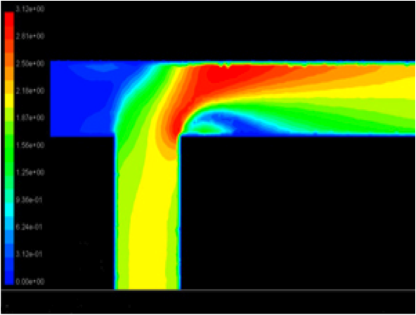 Fluid flows at
different velocities within a pipe's cross-section. For well-developed,
ideal flow, the fluid velocities will be highest near a pipe's center, decreasing towards the
pipe walls in symmetrical fashion. In the case of a 90 degree elbow or similar
union, the velocity profile is more complicated. The attached photo is a typical velocity profile for
a similar type of union. The blue areas indicate a lower velocity and the red areas are higher
velocities. Thus the effective cross-sectional area is reduced and the actual volume of fliud that will
pass thorough the pipe is reduced.
Fluid flows at
different velocities within a pipe's cross-section. For well-developed,
ideal flow, the fluid velocities will be highest near a pipe's center, decreasing towards the
pipe walls in symmetrical fashion. In the case of a 90 degree elbow or similar
union, the velocity profile is more complicated. The attached photo is a typical velocity profile for
a similar type of union. The blue areas indicate a lower velocity and the red areas are higher
velocities. Thus the effective cross-sectional area is reduced and the actual volume of fliud that will
pass thorough the pipe is reduced.
Another result of these turbulences is that the oil temperature increases. There is nothing good about a reduction in gallery diameter or a change in direction.
The length issue is best explained with an example. Most of us have tried blowing through a garden hose. Yes you can blow some air through a garden hose, but not nearly as much air as you can blow through a common straw - even through the straw is much smaller in diameter. We can only blow a small volume of air through that hose because the friction in the long hose overcomes the pressure we can create. The friction in the pipes of the typical community water system reduces the pressure so most customers do not have to have a pressure limiting valve, but those near the water tower almost always require such a valve. (With the relative short galleries in our FE block gallery length is not an issue. But if you add an oil cooler then the total length of the lines and the cooler galleries may become a problem if the line diameter is too small.)
So we need enough pump pressure to overcome the limits to flow induced by the size and tight corners of the galleries. The pump volume is that needed to supply enough oil to lubricate and cool the cam and crankshaft bearings for the stock engine. (The amount of oil for the other parts is a small percentage of the amount needed for these bearings. Typically we restrict the oil to the heads using two 0.070 or so orifices - about 5% of the area of the 7/16s main oil gallery.) This volume is largely determined by the clearances at the crankshaft main and rod journals. The stock bearing clearances of 0.0005 to 0.0027 with rod side clearances varying from 0.006 to 0.016 are adequately supplied by the stock pump at moderate engine RPMs. Note that the some 427 and 428 CJ clearances are higher. But increased clearances and higher loads for racing require that the oil system be reviewed.
It is standard practice to follow the rule of 10 pounds of pressure per thousand engine RPMs, but the low pressure light switch closes (turns the light on) at three to five pounds so a stock motor may have less than ten pounds of pressure.
A key point is that the pressure we see at the gauge (on an FE) is at the highest pressure point in the system. And this point is before the oil enters the main galleries. The further from the oil pump the lower the pressure - as the oil bleeds away at the bearings, around the lifters, etc., the pressure in the galleries drops. How much pressure and volume is needed is dependent on the how we change the galleries (Pressure) and bearing clearances we use (Volume).
Pressure and volume are linked together in an open system like we have in our engines. When the pressure increases the volume of oil delivered usually increases for a specific pipe diameter. But if the galleries are the restriction because of their size or shape then increasing the pressure or the volume available will not increase the amount of oil delivered. And if the pump's internal pressure by-pass is open because the galleries are the restriction, then the only way to increase the volume is by reworking the galleries to increase the flow through the galleries.
Number 1) is usually a correct but for race only, very high RPM (over 7500) motors or those motors with very wide clearances it probably is low. Those engines probably need higher pressure as the dynamic load on the rod bearings is very high.
The data in the chart below was provide by Doug aka pumpbldr and partially answers 2), above, by telling us the maximum pressure for a specific pump.
| M-57 | STD Volume | Yellow Spring | 40-45 psi | 1/4" Drive |
| M-57B | Std Volume | Brown/Plain Spring | 60-65 psi | 1/4" Drive |
| M-57HP | Std Volume | Big Blue Spring | 100-110 psi | 1/4" Drive |
| M-57HV | High Volume | Brown/Plain Spring | 60-65 psi | 1/4" Drive |
| M-57A | Std Volume | Brown/Plain Spring | 60-65 psi | 5/16" Drive |
| M-57AHV | High Volume | Brown/Plain Spring | 60-65 psi | 5/16" Drive |
Note that the outlet diameter of the FE pump is usually 7/16 inches in diameter. I've seen one no-name brand that was 13/32 and the Melling High Volume pump is 15/32.
If we know which pump we have and by watching oil pressure gauge our experience will tell us whether we need more pressure or more volume. But for those with limited experience it doesn't help a lot.
If our guess in 3), above, is correct and since failure of the rear main bearing is rare then if we improve the gallery any place enroute to the rear main bearing, it will increase flow to the rear main bearing. This leads us to 4). There are specific improvements to the galleries that reduce the restrictions and improve flow. Those are detailed in the Part Three.
Hydrodynamic lubrication or Fluid Film lubrication is the term used when a rotating shaft in a bearing is supported by a wedge of oil so the shaft is not in contact with the bearing. This is the same principle that allows a car to aquaplane on a wet highway. Aquaplaning occurs when the water gathers in front of the tires faster than the tire can push it out of the way. Your car then rides a layer of water between your tires and the highway. This requires a minimum rotational speed of the tires usually around 55 MPH. The tread style (or lack thereof on a worn tire) affects this speed also.
So the crankshaft rides on a wedge of oil. The oil is pushed to outside edges of the bearing as the crankshaft rotates but the pump continuously replaces the oil. This also allows the oil to cool the bearings. The journal design including the side clearance, crank speed, oil viscosity (here oil temperature comes into play), oil volume and oil pressure all effect this. Even the point where the oil is fed into the journal has a major impact on how well this works. In fact the rod journal fed hole is located so that the journal pulls oil from the fed hole as the crank rotates.
 The pressure varies across the bearing surface and is highest in the center of the bearing. If
the bearing shell has a groove then there are two surfaces with pressure highest in the center of each
side. The wider the bearing surface, the higher the pressure. The grooved bearing has less
surface due to the groove so the pressure is not as high on grooved bearings.
The pressure varies across the bearing surface and is highest in the center of the bearing. If
the bearing shell has a groove then there are two surfaces with pressure highest in the center of each
side. The wider the bearing surface, the higher the pressure. The grooved bearing has less
surface due to the groove so the pressure is not as high on grooved bearings.
The rod bearings likewise ride on a wedge of oil. This oil comes from a main bearing through a passage in the crankshaft. The rotation of the crankshaft causes a centrifugal force that helps to pump the oil out to the rod journals and, as stated previously, the placement of the hole in the rod journal allows the crankshaft's rotation to pull oil out of the passage. This good because when the cylinder fires the high combustion pressure tries to force the rod against the journal. Our modified engines with higher than stock combustion pressures really load the rod bearings and try to break down that wedge of oil. Good oil pressure is therefore needed at the rod journals.
These links have a more in depth discussion of hydrodynamic lubrication: Davidson University and Marine Diesel Information
To learn more about Engine Oil System Fundamentals you should download Internal Combustion Engine Lubrication which is a .pdf file.
Back to the top of Oil Modifications or ahead to Part Three - Modifications
This is a readable .pdf paper on Hydraulic Resistance with excellent graphics.
This part will review the specifics of the FE engines oiling system - gallery identification, gallery routing, gallery capacity, and volume requirements. The FE's oil galleries are shown in the Figure 1, below. The total number of twists and turns and changes in gallery dimensions gives the FE's oil system its poor reputation. I must state that for normal, every day use the stock oiling system works fine. The FE has no more oiling problems than any other American V-8.
(This Part does not include the 427 Sideoiler block.) First we need to label these galleries and passages. To my knowledge Ford hasn't named or labeled them but to make it easier to study them I have. Note that a gallery has one or more outlets along its length; a passage only has an inlet and an outlet. There are eight of galleries or passages which I will name.
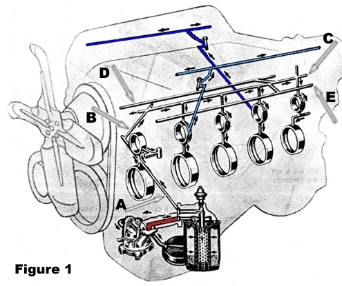
1) The Pump-to-Filter adapter -Passage, red in Figure 1 to the right, is almost always 3/8 of an inch in diameter but on some 428 CJs it is 7/16. This passage has turn of about 30 degrees about 1/2 an inch from the bottom of the block.
2) The Front-Gallery runs across the front of the block (Arrow A) starting at the filter adapter pad, past a passage that feeds the front (usually referred to as the #1) cam and main bearings and then ends about three inches later. This gallery is 7/16 of an inch in diameter.
3) The Front-to-Top-Passage (Arrow B) runs at an angle from the end of the top end of the Front-Passage to intersect the Top-Gallery in the lifter valley. This passage is 3/8 of an inch in diameter.
4) The Top-Gallery (Arrow C) runs the length of the engine in the center of the lifter valley. It is 3/8 of an inch in diameter. This gallery is drilled from both ends. One problem is that the drilled holes don't always meet properly. I've got a block which will only pass a 3/16 inch dowel in this gallery. So the two holes that meet to make this gallery almost line up. (To check the passages I suggest you buy a set of wood dowels or metal rods of 3/16, 1/4, 5/16, 3/8, and 7/16 of an inch in diameter. The wood set costs about $3.50.) The restriction is just in front of the #3 cam bearing about even with the center of the #6 cylinder's Intake Valve Lifter bore.
5) The Cam-&-Main-Bearing-Galleries feed the # 2, #3, #4 and #5 cam and main bearings. These galleries are each 5/16 of an inch in diameter.
6) The two Head-Passages feed the driver's (left) side rocker arms from a series of passages that start at the #2 cam bearing and goes to the deck of the block and then through the head. The passenger (right) side is similar but with the passage starting at the #4 cam bearing. These are in two shades of blue in Figure 1, above. The passage is drilled at an angel of 3 degrees to the deck. For the top part the passage is 5/16 inch in diameter but it steps down to 1/4 inch before it enters the groove behind the cam bearing.
7) and 8) These are the two lifter galleries - Right-Lifter-Gallery (Arrow D) and Left-Lifter- Gallery (Arrow E) that run the length of the block. (Left and right are always from viewpoint of someone in the driver's seat.) These galleries are connected the Top-Gallery by short passages about four inches from the back of the lifter valley. The diameter for all of these measures 3/8 of an inch.
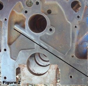
The oil is pulled out of the pan by the pump, comes out of the pump at the mounting pad at the front left corner of the crankcase, enters the Pump-to-Filter-Passage which routes the oil to the filter adapter on the outside of the engine. After the oil goes through the filter it enters the Front-Gallery which takes it to the right of the front cam bearing. Figure 2 shows the front of the block and I've placed a heavy black line just below the Front-Gallery. It feeds the #1 cam and main bearings through a 5/16 passage. At top end of the Front-Gallery the oil enters the Front-to-Top-Passage. The tight (90 degree) corner where the oil turns from the front of the block and goes into Front-to-Top-Passage is the main restriction in the standard block's oiling system. The Front-to-Top-Passage goes up to the Top-Gallery which is the main distribution gallery and feeds the Cam-&-Main-Bearing-Galleries and the Lifter Galleries.
The Cam-&-Main-Bearing-Galleries feed the # 2, #3, #4 and #5 cam and main bearings. The cam bearings are fed first as they are between the Top-Gallery and the main bearings. While this routing gives priority to the cam bearings, it not uncommon to route the oil in this manner. The small block Chevrolet does it this way also.
Because the main bearing journals and crankshaft journals are not spaced the same and the fed holes to the cam bearings must be centered on the groove behind the cam bearings, the holes in the #1, #2 and #4 main bearing saddles are not centered. Ford issued a technical bulletin on this and the mid-'60s shop manuals addressed it as well. Jay Brown: If you are using stock type bearings, with the oil hole in the bearings rather than the oil slot, this is not an issue, and has been addressed by Ford and posters on the FE Forum. If you are using the "good" Federal Mogul main bearings, which have a slot rather than an oil hole in the bearings, then the modification will be required. Jay Brown This issue will be addressed again in Part Three.
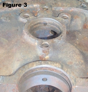
For the center three cam/main bearing pairs there is a drilled hole from the main bearing to the Top-Gallery. The #5 main bearing passage is different because the rear main bearing is not at the rear of the crankshaft. In order to have room for the rear main seal, the rear main bearing is located about 5/8 of an inch forward which requires the two 90 degree turns in this passage as shown in the Figure 1. There is also a circular groove under the #2, #3, #4 and # 5 cam bearings for the oil to travel to the passage leading to the respective main bearings. Figure 3 shows the rear face of the block with the #5 cam (upper) and main bearing (lower) bores. The groove behind the cam bearing can be seen in the upper bore.
Near the back of the block the Top-Gallery feeds two short passages, one on each side of the lifter valley. These passages go to the Right-Lifter and Left-Lifter-Galleries.
The #1 (front) cam bearing has an outlet that feeds the distributor gear. The #2 cam bearing feeds the driver's side head through the Head Passage. The head has a groove in its deck that goes to a passage along one head bolt. There is a short passage from the head bolt hole to the base of the second (from the front) rocker arm assembly bolt. Oil then runs up the hole in the rocker arm assembly stand to the rocker arm shaft. The passenger (right) side is similar but with the passage starting at the #4 cam bearing, and going up the second from the back rocker arm stand bolt.
Some early 1958 blocks did not have the galleries drilled the feed the hydraulic lifters because these engines used solid lifters. Blocks marked "HP" plus all 427 blocks through 1967 were not drilled for hydraulic lifters.
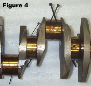
What Figure 1 does not show is the routing of the oil through the crankshaft to the rod bearings. The front main bearing journal has one hole that feeds the front, #1, rod journal. The rear main feeds the #8 connecting journal. The center three main bearing journals each feed two rod journals, one to the front and one to the rear. Figure 4 shows zip ties inserted into a crankshaft's rod journal's passages with the two crossed zip ties going from a single rod journal into different main bearing journals. The third zip tie is going from the second passage in the left main journal to the rod journal on the other side.
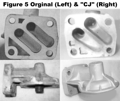
The standard car oil filter adapter mounts the oil filter vertically. Starting in 1968 the passages in the adapter that fit against the block were revised becoming much deeper. The revised one is often referred to as the 428CJ adapter but this is incorrect as the adapter was used all car engines. Figure 5 shows both of these adapters. You can see the difference as the outside face of the "CJ" adapter is raised to accommodate these deeper passages. There is no reason to use the older adapter unless you are building a numbers correct car that you will not race.
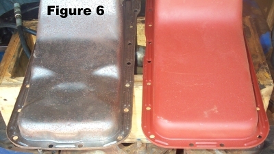
Other than depth all factory oil pans are very similar. There are two main differences. The first is variations in the oil scrapers and baffles. The bottom line is that none of these scraper variations is considered to be any better than the others.
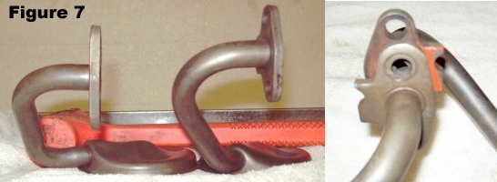
The second difference is a pair of indents or dimples to clear the inner tie rod ends on the pans used on the Mustangs Cougars, Comets and Fairlanes. These pans were also shallower and used a different oil pickup tube. Figures 6 and 7 show these differences.
Hard acceleration causes the oil in the pan to move to the rear, away from oil pump pick up. This starves the oil pump allowing it to only pump air. The 428 CJ engine oil pan configuration was changed during the model year to fix this problem. A windage tray was added, and since the windage tray keeps the oil off the crankshaft, this allowed an extra quart of oil to be added. The dip stick was changed to reflect the higher oil level. These changes largely solved the problem of air entering the oil pump.
One question is just where does the oil go? In our FEs it leaks out at the edges of the cam, main and rod bearings as well as the top and bottom edges of the lifters and the edges of the rocker arms. (I'm ignoring the loss through the hydraulic lifters.) There are exactly 100 such leak sites - five crankshaft main bearings, each with two edges (10); five camshaft bearings, each with two edges (10); eight rod bearings, each with two edges (16); sixteen lifters, each that leak at the top and bottom edges (32); and 16 rocker arms, each that leak on both sides (32).
The total area for these leaks is found by calculating the area of the bearing bore (or lifter bore or rocker arm bore) and then subtracting the area of the journal (or lifter or rocker arm shaft diameter). The average of allowable the factory clearances for the main and rod bearings (0.0015), cam bearings (0.0015), lifters (0.001), and rocker arms (0.004) are typical of the clearances used by many of us. The following a chart to clarifies and summarizes this.
The far right column, Percent of the Total, is most revealing. I was very surprised to see the high percentage of oil that came out at the rocker arms. This should not have been unexpected as the typical rocker arm clearance is relatively loose. The bottom table shows the rocker arm flow reduced by using a pair of 0.070 jets as restrictions, decreasing the effective opening from 40% of the total to only 3% of the total. This reduces the total leak area of the engine by 38%, and provides a higher percentage of the oil volume to the bearings.
A gallery's theoretical size requirement is equal to the cross sectional area that matches that of the related down stream leak areas. We will calculate the need at the far end of the FE's oil gallery, and work our way to the Front-Gallery creating a running total of the area increases as we go. We will also track the growth in the needed gallery diameter as we work our way to the oil pump.
The rear or #5 Cam-&-Main-Bearing-Gallery feeds the #5 cam bearing, #5 main bearing and #8 rod bearing. From the chart above we get an area for each edge of 0.0050 for the cam bearing, 0.0065 for the main bearing and 0.0057 for the rod bearing. We need to double each of these as each bearing has two edges. The total ((0.0050 + 0.0065 + 0.0057) times 2) is 0.0345 square inches which calculates to a diameter of 0.2095 inches (less than 1/4 inch). Thus the #5 Cam-&-Main-Bearing-Gallery should have a minimum diameter of 1/4 inch and the rear of the Top-Gallery would, of course have the same minimum diameter.
Figure 1 shows that the two Lifter-Galleries feed off the Top-Gallery before we get to the #4 Cam-&-Main-Bearing-Gallery. Each lifter has a area of 0.0014 at each end so the 16 lifters have a total area of (0.0014 times 2 times 16) of 0.0448. Adding this to the previous area our running total is now 0.0793 square inches or a gallery diameter of 0.3177 (less than 3/8 or 0.375.)
The #4 Cam-&-Main-Bearing-Gallery feeds the #4 cam bearing, #4 main bearing and #4 and #7 rod bearings and the right head passage that goes to the passenger's side rocker arm assembly. Calculating this as before, we get 0.0537 square inches for the leak area for this gallery. Adding this to the previous total our running total is now 0.1329 square inches or a gallery diameter of 0.4114 (somewhat less than 7/16 or 0.4375.)
The #3 Cam-&-Main-Bearing-Gallery feeds the #3 cam bearing, #3 main bearing and #3 and #6 rod bearings. Calculating this as before, we get 0.0460 square inches for the leak area for this gallery. Adding this to the previous total our running total is now 0.1789 square inches or a gallery diameter of 0.4772 (less than 1/2 inch.)
The #2 Cam-&-Main-Bearing-Gallery feeds the #2 cam bearing, #2 main bearing and #2 and #5 rod bearings and the left head passage that goes to the driver's side rocker arm assembly. Calculating this as before, we get 0.0537 square inches for the leak area for this gallery. Adding this to the previous total our running total is now 0.2345 square inches or a gallery diameter of 0.5441 (less than 9/16 or 0.5625.)
The Front-Gallery feeds the #1 cam and #1 main bearing and #1 rod bearing. Calculating these as before, we get an additional 0.0345 square inches for the leak area. Adding this to our running total we have 0.2670 square inches or a gallery diameter of 0.5830 (less than 5/8 or 0.625.)
This chart summarizes all of the above.
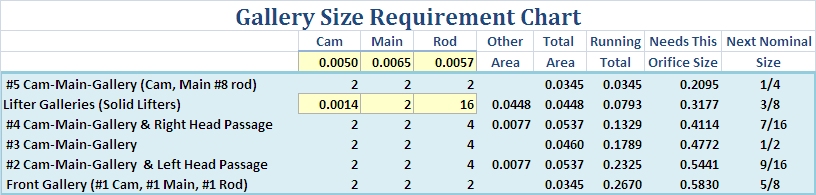
The above numbers show that, in theory, our Top-Gallery is only 70% of the size it should be and the Front-Gallery is only 75% of the size it should be. Since the leak area is so large compared to the gallery size how does the engine have any oil pressure? Well, the leak area at the main and rod bearings is not just a opening to the air but rather a very thin ring 0.0015 inches thick (less than half the thickness of a sheet of paper). The oil must make a sharp turn just before spreading out to travel through this restrictive 0.0015 inch thick (actually quite thin) ring with a width 300 times longer that it is thick (half of the .0.907 inch bearing width). That paper thin ring's shape is the real restriction.
Despite the gallery size and shape limitations, the oil pump is still able to deliver sufficient oil to lubricate and cool the engine. The oil pressure overcomes the small galleries by forcing the oil through them. In fact the high volume pump uses the same galleries and delivers enough oil to successfully lubricate main and rod bearings with clearances in the 0.004 range.
We now know why Ford developed the Sideoiler. When you open up the bearing clearances to cool the bearings for a long distance (NASCAR) racing motor, the oil volume requirement goes up and the restriction of the stock galleries only gets worse. Revising the oiling system, so that the main bearings got oiled first, puts much more pressure at the rod bearings.
(I have not calculated the required gallons per minute for the above requirements and therefore have not compared that to the volume of output available from the standard or high volume pump. I may do that in the future or I someone wants to do that and provide it to me I will add that information.)
Back to the top of Part One - Engine Oil System Theory or Part Two - The FE's Oiling System
Hopefully I didn't lose too many people in the first two parts of this topic. At the end of Part Two I showed that the standard top oiling FE does not have the theoretical gallery sizes needed to properly supply oil to the engine and, thus, why Ford went to the Sideoiler. But with lots of people successfully racing the FE using the standard bloc, how are these Racers modifying their oil systems? What should be done and exactly where should it be done?
Obviously we have to improve the oil system to match the intended use. I have researched what is being done, re-read all the threads all the related on the forum and have talked to several FE race engine builders from the late '60s. I thought I could now state my conclusions and be done.When I had this reviewed by several other senior forum members I got responses that fell into two categories: 1) Wow - Never looked at all of that before and 2) So What - You're working too hard. The first group found my analysis and conclusions useful and the second thought I'd lost my mind.
The second group agreed that while changes could be made to the oil galleries, they never had and probably never would - their cure was a high pressure pump or a high volume pump or if necessary a high volume/high pressure pump. Let the pump overcome the inherent weaknesses of the Ford design by brut force. The other changes they always made were: 1) restrict the oil to the heads because the oil drain back could be flooded if the flow was not restricted and 2) add a windage tray and baffled oil pan to keep the oil around the pick-up at all times.
Not exactly what I would call a consensus. And looking the successes of both groups, they are both correct. You can rework the galleries or not. If not then you will probably need a higher pressure pump. Yes, the block has galleries that are not optimal. Get out the drill and grinder and fix them and then make the changes in the pan because if the pickup goes dry everything else was a waste of time.
First, verify that the top gallery is drilled properly - that a 3/8 rod will go completely through the block. If the rod won't go through find another block or get the block drilled to fix this.
1. Restrict the flow of oil to the rocker arms using #69 (0.070 hole size) Holley jets under the rocker arm stands. Actually any pair of jets size between #60 and #70 would be fine. I have seen jets as small as #43 and as large as #90 used for this but if you are going to buy some, 69 is an easy number to remember.
2. Open up the oil pump to oil filter adapter pad gallery from 3/8 to at least 7/16 of an inch and smooth and round the opening on the pump end and both holes on the adapter pad end. There is no reason to have this restriction at the front of the oiling system. The front gallery is 7/16 and this one should be 7/16 also. Goodson makes a Piloted Core Reamer (normally used to cut out old valve guides) that has a .371 pilot tip and a 0.490 body that I use for this. This tool costs about $100.00 today.3. Use the late model "CJ" oil filter adapter.
4. Install a windage tray so you can add an extra quart of oil to the pan without the oil whipping around with the crankshaft and re-mark the dip stick. SHOE The number one oiling mod for any fast "somewhere-in-the-14-second-bracket" FE (with stock front sump pan) is to run six quarts of oil. On Friday I watched a 428CJ Mustang destroy some rod bearings at the end of the drag strip because he had an early CJ which still had the old 5-quart dipstick (not the "service bulletin" 6-quart dipstick used in later CJs). He's run 180+ passes with 6-quarts, and this is the first time he forgot to add the extra quart. SHOE
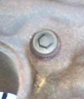
 5. Open up the oil returns on the heads. That big hole is almost blocked by the head bolt;
however, the outside of the head is solid and may be opened as shown. If the returns are not large
enough, oil gets trapped in the head. It's not unheard of for a quart of oil to be pooled in each
valve cover.
5. Open up the oil returns on the heads. That big hole is almost blocked by the head bolt;
however, the outside of the head is solid and may be opened as shown. If the returns are not large
enough, oil gets trapped in the head. It's not unheard of for a quart of oil to be pooled in each
valve cover.
SHOE: Be sure the corner back passages in the heads are clear. Old rebuilds frequently have petrified "umbrella type" rubber valve seals which chip-apart and restrict drain back. Similarly, excess gasket sealer or silicone seal at the rear corners of the intake manifold can restrict the rocker oil return flow. If your FE smokes or uses oil unexpectedly, it's likely due to excess oil gathering at the rear of the head. This is particularly true when high volume pumps are used. SHOE
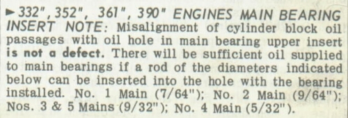 There is one issue that seems needs to be revisited before we go any further. There is a
misalignment of the holes in the #2 and #4 main bearing saddles and the holes in the bearing shells.
This due because the cam bearing spacing and the crankshaft bearing spacing are slightly
different. This is not normally a problem for street engines with bearing clearances of 0.002
or less. Ford issued a Service bulletin about this and an extract of that Service bulletin is at
the right. All bearings that you can buy today provide on opening big enough to meet the
requirement in the technical bulletin.
There is one issue that seems needs to be revisited before we go any further. There is a
misalignment of the holes in the #2 and #4 main bearing saddles and the holes in the bearing shells.
This due because the cam bearing spacing and the crankshaft bearing spacing are slightly
different. This is not normally a problem for street engines with bearing clearances of 0.002
or less. Ford issued a Service bulletin about this and an extract of that Service bulletin is at
the right. All bearings that you can buy today provide on opening big enough to meet the
requirement in the technical bulletin.
If you are going to use large main and rod bearing clearances these are essential. Anything we can do that will improve the capacity of the galleries at minimal cost should be done.
 1. Open the oil holes in the # 2 and #4 main bearing saddles so they are as large as the hole
in the bearings. This is one of the controversial modifications. The picture shows a bearing
saddle from a 1970 427 Sideolier service block. The medium duty trucks were also drilled/reamed as
shown. There has been a great deal of discussion about whether this is necessary or not. When
the block has been very heavily stressed either from nitrous or
just many runs down the track it is not unheard of for the block to crack through the holes in the main
bearing saddles especially if they've been opened up deep into the saddle. As a result most engine
builders don't recommend re-drilling the hole to make them bigger and many won't even grind the end of
the hole. Instead they open up the hole in the bearing.
1. Open the oil holes in the # 2 and #4 main bearing saddles so they are as large as the hole
in the bearings. This is one of the controversial modifications. The picture shows a bearing
saddle from a 1970 427 Sideolier service block. The medium duty trucks were also drilled/reamed as
shown. There has been a great deal of discussion about whether this is necessary or not. When
the block has been very heavily stressed either from nitrous or
just many runs down the track it is not unheard of for the block to crack through the holes in the main
bearing saddles especially if they've been opened up deep into the saddle. As a result most engine
builders don't recommend re-drilling the hole to make them bigger and many won't even grind the end of
the hole. Instead they open up the hole in the bearing.
While I at first agreed that opening up the bearing was a good solution I forgot what the decreased surface area does to the oil pressure pattern across the face of the bearing. After reviewing Hydrodynamic Lubrication and the related bearing pressure graphs I believe the bearing surface should remain as wide as possible. I now recommend the bearing saddle be opened up with a die grinder but not deeper than 1/4 inch or so and polish the opening to reduce the tendency for a crack to start.
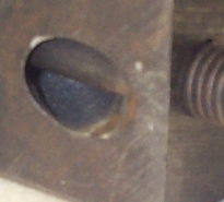
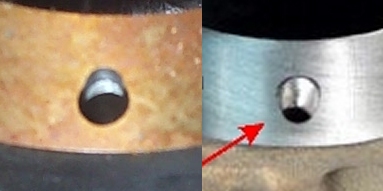
 2. Drill and tap all oil gallery plugs for screw in plugs. The factory started doing this
in the '68 time frame. Warning the plug installed in the accompanying picture is installed so deep
that only a 1/4 inch rod will go through the Top-Gallery. That plug is now blocking the top
gallery. The plugs must not be installed that deep.
2. Drill and tap all oil gallery plugs for screw in plugs. The factory started doing this
in the '68 time frame. Warning the plug installed in the accompanying picture is installed so deep
that only a 1/4 inch rod will go through the Top-Gallery. That plug is now blocking the top
gallery. The plugs must not be installed that deep.
3. Install a baffled oil pan to prevent your oil pressure from going down during acceleration because the oil is sloshing to the rear of the pan away from the oil pickup screen. A baffled pan will also reduce the chance of air to entering the pump due to the oil moving away from the pick-up as the vehicle pitches and rolls in normal driving with a shallow pan.
SHOE: Replace the stock 5-quart pan with a baffled pan (many T-pans offer baffles and extra capacity with stock ground clearance) and matching oil pick-up. If you even THINK of installing a performance oil pump before installing a performance pan and matching oil pickup in your front-sump FE, you may be making an expensive mistake. Performance oil pumps will only work with stock front-sump pans if your FE car is a sled. Fast FEs with stock pans and performance pumps have sufficient acceleration to slosh too much sump oil to the rear of the engine, causing the performance pump to pump air, albeit highly compressed air. Pumping air is the most common reason for FE oiling failures. SHOE
4. Install a high volume pump (Melling -57HV) and install an after market heavy duty oil pump drive shaft. SHOE: Also, you need to check your distributor to make sure you don't have a rebuilt one with the ultra common (ultra cheap) "rolled" shear pin, as these pins need to be either stock solid pins or rebuilt with solid pins (special order) to handle the pounding of a performance pump. SHOE
Based on my Leak Area analysis I highly recommend the use of a Sideoiler block. There is no easier way to feed enough oil to keep the engine alive. That said, many people do fine with the standard top oiling FE. So let's look at what we can do to get the best flow with the least pressure.
Open up the Pump-To-Filter-Passage to at least 15/32. One-half-inch is better and the block has enough meat that this usually isn't a problem. Use the "CJ" oil filter adapter. Eliminate the sharp corners into the passages that are under the Adapter by rounding them off with a grinder.
The Front-Gallery is only 7/16 of an inch but the Front-To-Top-Passage is only 3/8 with a tight, 90 degree turn where they intersect. And you can't see the intersection to round it off with a grinder. Without a doubt this is a major restriction.
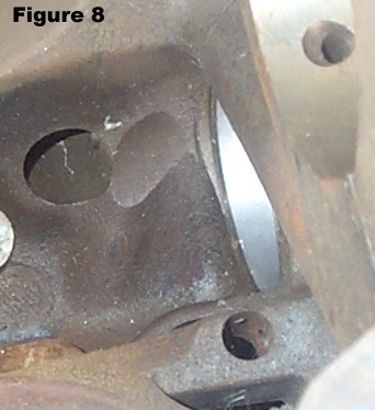
The 3/8 of an inch Front-To-Top-Passage runs between the cam bore and the front lifter. You can see that the bottom of this gallery is machined for cam lobe clearance in Figure 8 at the right. How much bigger this passage can get reliably is unknown to me but I once drilled it out to one-half inch without breaking through. I think that the block thickness should be checked with a sonic checker in that machined area prior to drilling out the Front-to-Top-Gallery a drilling it makes the bottom of the passage wall thin and it may crack or split under pressure.
I want to state that many successful Racers get by with few modifications to the block. They open up the Pump-To-Filter-Passage to 7/16 of an inch, install restrictors, enlarge the head drain backs, install threaded plugs instead of press in plugs and use a high volume/high pressure volume pump. They install a deep or baffled pan and windage tray with the correct dipstick. That's it. Period.
Ford didn't drill the hydraulic lifter galleries for their solid lifter cammed engines. The question is asked regularly about whether these galleries should be blocked on our the FE's when converting to a solid lifter cam.
It has been reliably reported that Ford tested their cams extensively to insure that the opening (and closing) ramps of the cam lobes were designed to prevent valve float. The old style factory flat tappet cams had very slow ramp rates and the weak factory valve springs - that by comparison to today's valve springs - did not create near the load on the valve train that today's aggressive cam and valve spring combinations create. Less load allowed splash lubrication. With the higher loads of today that may not be adequate so I never block the hydraulic lifter galleries.
Many people do block these galleries but for an entirely different reason. If you bend a push rod and throw a lifter out of the bore and you did not block the galleries you can lose oil pressure and destroy the engine. Either choice is right; it just depends on your point of view.
There is a mistake that appeared in an issue of the FECA (FE Club of America) newsletter.
If you use dumbbell lifters the oil would dump out the oil passages to the lifters due to the dumbbell
shape. You must use either a standard style lifter or the shell type lifters to restrict the oil.
Jay: Dumbbell lifters won't cause oil to "dump out of the passages
due to the dumbbell shape". The gap between the lifter bore and the lifter fills up with oil, but
then this oil has to escape into the engine through the clearance volume between the lifter body and the
block. Using straight lifters will not result in any less leakage in this area than using dumbbell
lifters, assuming the same fit between the lifters and the bores. Dumbbell lifters have been
successfully used by myself and many others on thousands of FEs; they do not cause internal oil leaks.
Jay
For those that want to see some other options in the Leak Analysis here are some leak area comparisons first using the standard FE bearings with clearances of 0.0015, 0.0025 and 0.0035 and then using the big block Chevrolet rod journal size as used in most stroker kits with the same clearances.
These are some related threads from the forum.
Jerry Pitts article in Mustangs and Fords. Shoe's unedited thoughts which are used extensively above. Discussion about the Mustang & Fords article. A High Pressure versus High Volume Pump Discussion. Oil modifications and block machining thread. Shoe's documents on 427 and Sideoiler factory plugs.
(If you have a related link that I missed, please forward it to me so I may add it.)