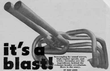
180 Degree Headers
There's a trick Ford first used at LeMans with the 289 and later the 427 engines routing the exhaust through a "bundle of snakes" behind the engines, see the below picture.
180 Degree Headers
The exhaust from two cylinders is routed to join with two cylinders from the other side of the engine so those cylinders that fire 360 degrees apart are paired. This isn't east to do and its logic is not obvious but stay with me and I'll try to explain it.
The firing order of the FE is 1-5-4-2-6-3-7-8 and cylinder numbers are 1234 on the passenger side and are 5678 on the drivers side, front to rear. Looking at the firing sequence the passenger side is 1-4-2-3 and the driver's side is 5-6-7-8.
Remember that the four stroke internal combustion engine takes two complete revolutions to go through the four strokes: piston down for intake, piston up for compression, piston down for power and piston up for exhaust.
On the Ford FE engines, Cylinder No. 1 fires, the crank rotates 90 degrees, No. 5 fires, etc. So on the passenger side of the engine No. 1 fires, followed 180 degrees of crank rotation later by 4, 90 degrees to 2, 180 degrees to number 3 and 270 degrees to get back to No. 1. On the drivers side 5 fires first then 270 degrees to 6, 180 degrees to 7, 90 degrees to 8 and 180 degrees to get back to No. 5. (This uneven firing is called secondary imbalance and it's the main reason for motor mounts; if the engine was bolted down tight, the vibrations would stop most of us from riding very far, and one of the reasons NASCAR drivers are exhausted after a race.) But the problem is that cylinders 7 and 8 as well as 2 and 4 fire too close together, only 90 degrees apart.
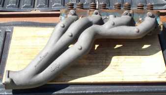
Typical 427 Big Car Manifolds '63-'64
In the above picture are the 427 Tri-Y manifolds used in 1962-64 Galaxies. The paired cylinders, 1 with 2 and 3 with 4, fire 270 then 450 degrees apart. The same is true on the other side of the engine where the two paired cylinders are 5 with 7 and 6 with 8. This is good but the ideal is firing 360 degrees apart. That would be 1 with 6, 5 with 3, 4 with 7 and 2 with 8. Which is difficult since half of each pair is not on the same side of the engine!
Back in the late '60s this is what Doug's Headers and Jardine Headers tried to accomplish by routing a couple of cylinders from one side of the engine (collector) to the other. This was done to balance the exhaust pulses for more power (and solving the problem of how to keep the length of the two rear most header pipes close to the length of the front ones). We want to pair cylinders firing 360 degrees apart. By routing No. 8 and No. 4 to the other side of the engine we can pair 2 with 8 and 4 with 7 so we are half way there and we eliminate the 7-8 and 4-2 problems. And we pair 1 and 3 which fire 450 then 270 degrees apart and 5 with 6 which fire 270 then 450 degrees apart. Fifty percent better.
Again remember that we would like all of our header pipes to be the same length. It is hard to get the pipes from the two rear cylinders to be long enough and also fairly straight. By routing them to the other side of the engine we help solve this problem as well.
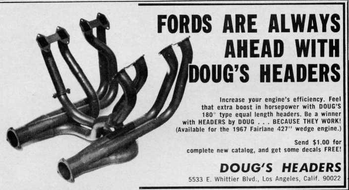
Again Doug's Headers and Jardine Headers manufactured the cross under header, see the below ad from 1969 (or so).
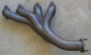
180 Degree Headers for the '66-'69 Fairlane
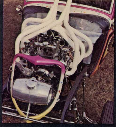
180 Degree Headers Revisited
The last photo, above, from the late '60s or '70s shows that one drag racer really believed in this stuff. I apologized that the engine is a Ch*$y but I could not find picture of an FE engine with this type of header.
For those of you that want to know more about the design of equal length headers for Race engines see Scientific Design of Exhaust and Intake Systems by Philip H. Smith and John C. Morrison, published by Robert Bently, Inc., Cambridge Massachusetts 02138.
The length of the header pipes, their diameter and the collector is a discussion that takes this book of almost three hundred pages to cover. To give you a bit of insight into the problem of race header design, remember that at 3000 RPM the exhaust pulse only has .01 of a second to get out of the cylinder. [60 seconds / (3000 RPM) / 2 Note: one-half revolution, just the up stroke.] So at 6000 RPM the exhaust port delivers a string of .005 second duration exhaust pulses every .02 seconds. Or a pulse for .005 of a second and then dead air for .015 seconds. And we want the exhaust pulse to help the intake side of the engine during the period that both the intake and exhaust valves are open. Not a trivial problem.